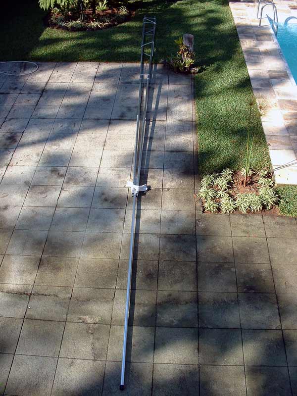
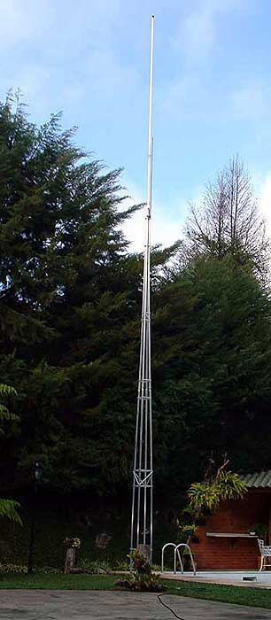
This self-supported vertical antenna was made with aluminum tubes of 3 m in length that have an external diameter of 1 1/4" (32 mm) and a wall thickness of 1.2 mm. The total length of the radiating system is 10.75 m and its square-shaped base measures 25 cm on a side.
To the theoretical length (1/4 lambda) was added 5% due to the width of the antenna.
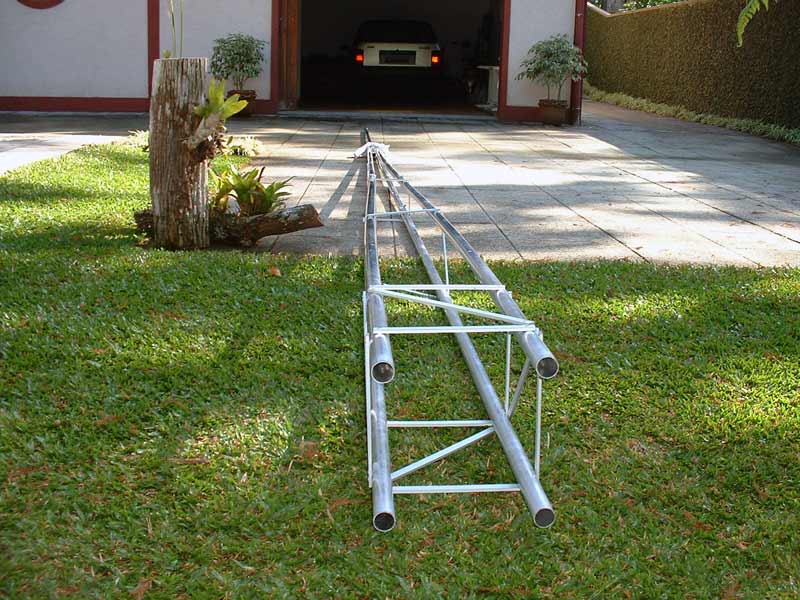
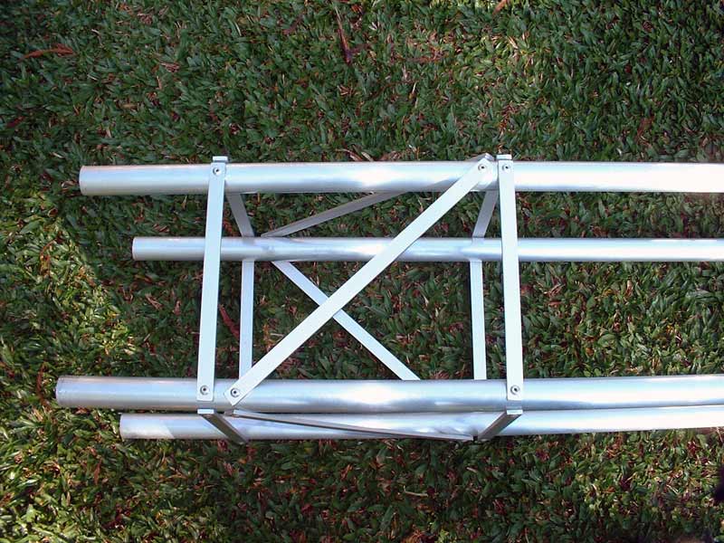
The various lateral stabilizing and connecting rods of the tower are made from rectangular shaped aluminum bar (17.0 mm x 6.5 mm) and are secured to the tubes with pop-rivets that are 1/2"x 3/16" in diameter.
Those rivets are much better than bolts and nuts - completely free of galvanic corrosion (same metal) and the pressure achieved with an hand tool will be more than sufficient to make a solid mechanical and electrical connection good for many years.
Here is a summarized list of materials: a total of nine (9) 3.0 m aluminum tubes have been used, one (1) 50mm diameter PVC tube, 2.5 m in length, 12 meters of aluminum bar (the stabilizing rods), 140 aluminum pop-rivets, and 9 inox steel braces of 45 mm in diameter.
The total weight of the radiating system is less than 15 kg, perfectly supporting winds of 90 Km/h as a lower limit in a computerized simulation and without the necessity of stays.
Since the revision date of this article, the antenna is already more than 15 years old and its efficiency is the same as when it was mounted.
The unions between the aluminum tubes was made with small pieces of copper pipe 20 cm in length and whose external diameters fit perfectly in the interiors of the aluminum tubes.
Small longitudinal “ridge” cuts (10 mm) on the tips of the aluminum tubes have allowed them to be firmly pressed, with the inox steel braces, onto the copper pipes and make good electric and mechanical contact.
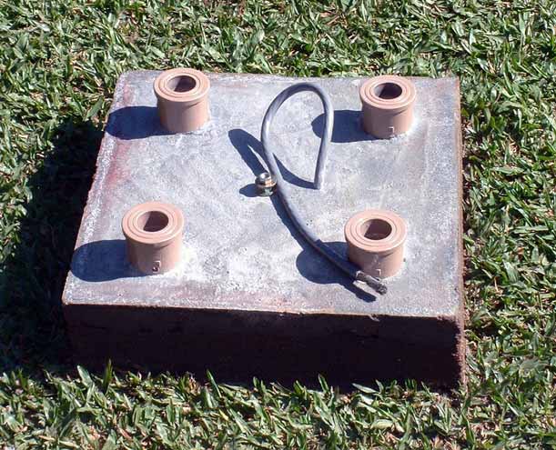
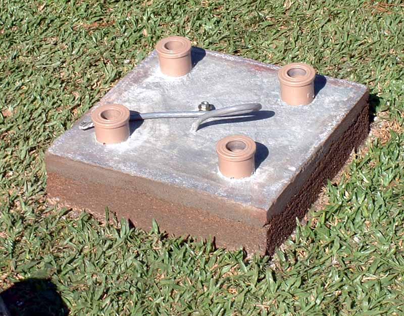
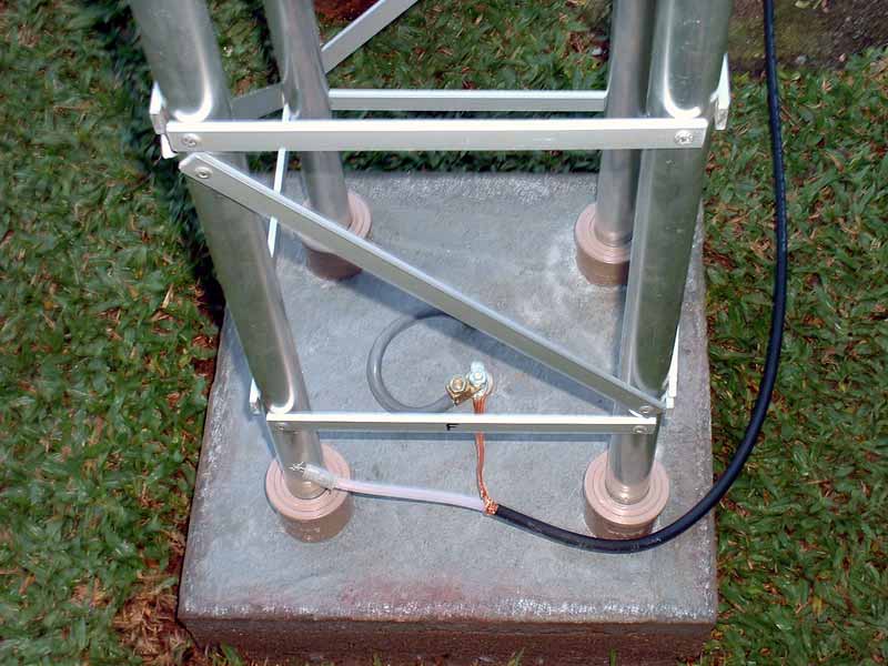
The four insulators of the base of the antenna are made with Brazilian "TIGRE" PVC reducer unions.
Four (4) sections of weldable PVC (brown core), 50 mm in diameter have been used, with 60 cm of length embedded in the center of the concrete base and on the exterior tips (80 mm) two reducer unions have been joined with "TIGRE" PVC glue.
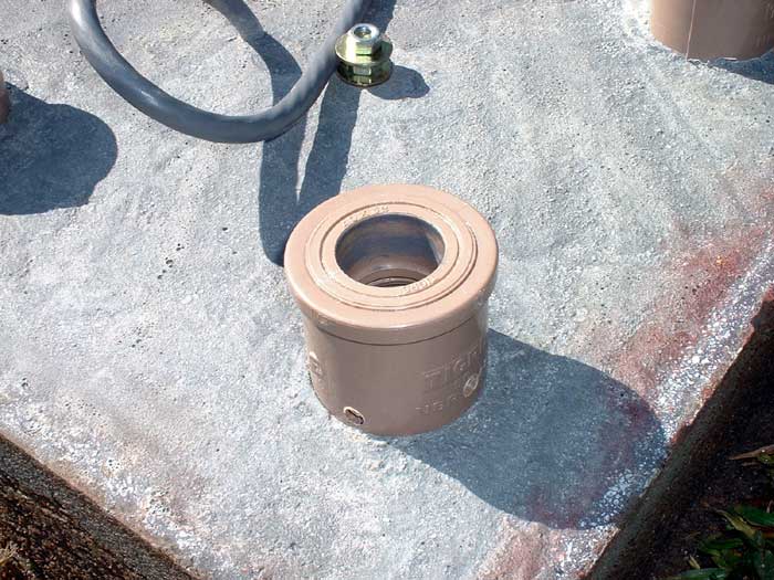
In the center are positioned 32/40 mm reducers that are then coupled via 40/50mm reducers to the 50 mm diameter PVC.
Glue is also applied on the tip of the pipe displayed above of the concrete mass.
In these insulators the four feet of the antenna are placed.
They are introduced 30 mm inside of the lesser sleeve, until they're jammed inside.
Completing the setting, four screws of 3/16" x 2" cross the interior of each insulator, thus securing the antenna to the support.
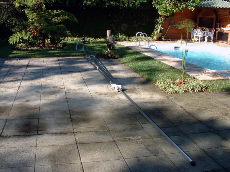
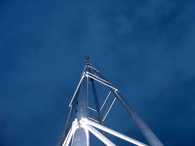
The tower properly set has an upper part formed by a 6 m mast with a single tube sliding portion of 5m by which Standing Wave Ratio (SWR) adjustments can be made. After the adjustment, single inox steel brace will keep the upper mast in position.
The support insulator was buried to the soil with concrete (cement, rock dust, and 20mm stone aggregate at ratio of 1:4:4) in a squared hole of 40 cm width and 80 cm deep. In the deep end of the hole four linked 2.4 m copperweld poles had been inserted and interconnected with 25 mm2 flexible cable so they will be part of the grounding.
Measurements made with a milli-ohmmeter resulted in a 3.6 ohm when all the poles were in place.
Beyond the copperweld poles, a system of 13 radial of 10 m length, using sections of flexible copper wire (1.5 mm in 2 sections) were attached to the ground terminal.
These wires are embedded and hidden to a depth of 10 cm underground and complete the grounding.
The fact that, as embedded, the radials lose their resonance means that their exact length is not very significant.
However, their combined effect on impedance is not negligible. In practice, the ground impedance obtained was around 20 ohms.
This was then added to the theoretical impedance (35 ohms) of the 1/4 wave antenna which then became close to the 50 ohms necessary for correct adaptation to the coax cable RG-213. With the low Q of the antenna, the SWR over the whole band was well below 1.2:1.
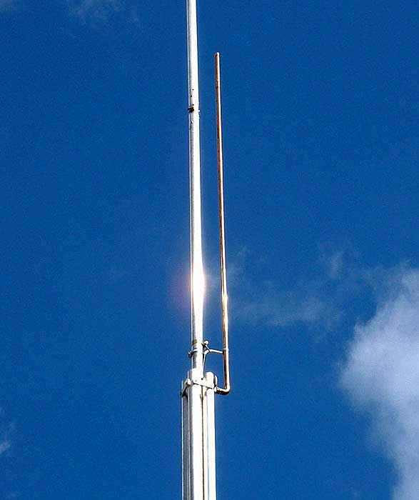
In the top, an element was placed as a driver for the 50 MHz band, transforming the upper part of the antenna to a 1/2 wave radiator for 6 meters (3 Db of gain over isotropic). The J-Pole was made with copper pipe of 15 mm diameter and whose length was 1.47 m. It has an independent coax cable of RG-213 that goes down into the interior of one of the tubes of the antenna. This element for 50 MHz does not interfere with the main antenna that continues to resonate at 7 MHz. The SWR at 50.500 MHz is 1.0:1 and reaches 1.2:1 between 50.000 and 51.000 MHz.
My next experiment will be in making a radiating system with a J-Pole for 10 meters whose photos will be published upon its successful completion.
73, Sergio Valente, PY1ZA
|